
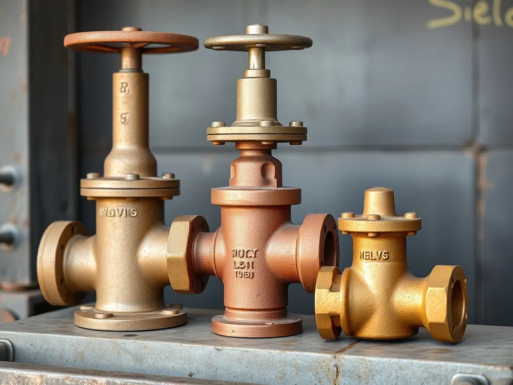
Iron and Steel Valves
used in water control and flow management
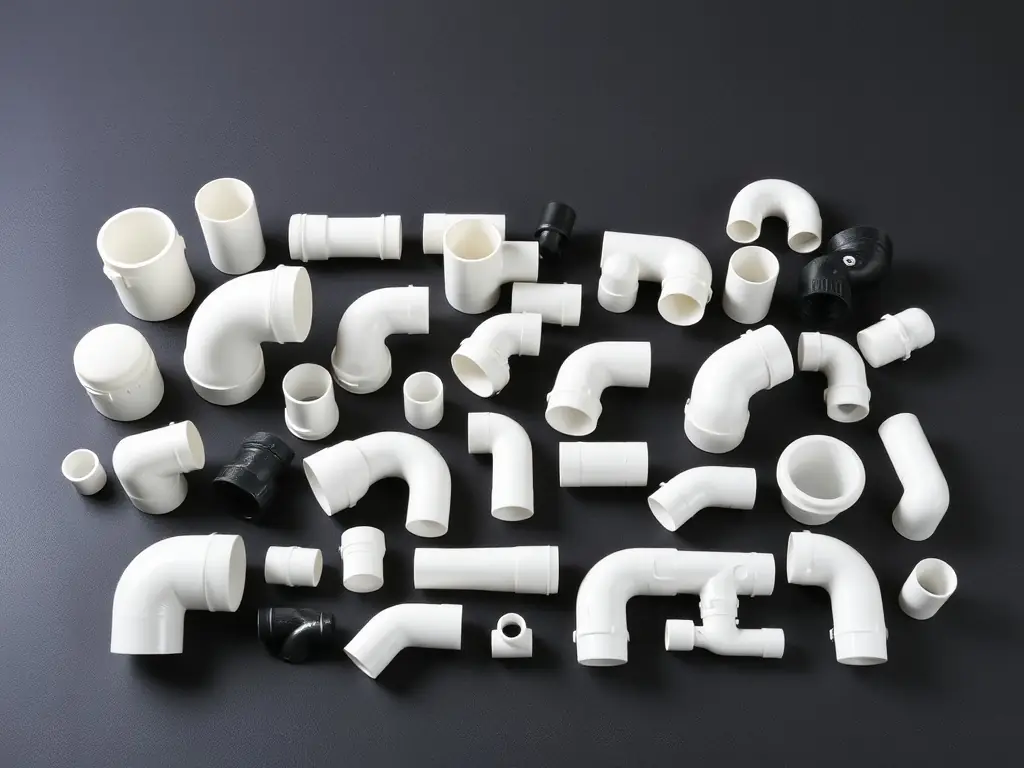
Polyethylene Fittings
We provide a comprehensive selection of electrofusion and injection fittings designed for creating robust and leak-proof water networks. These fittings ensure reliable connections and optimal system performance.
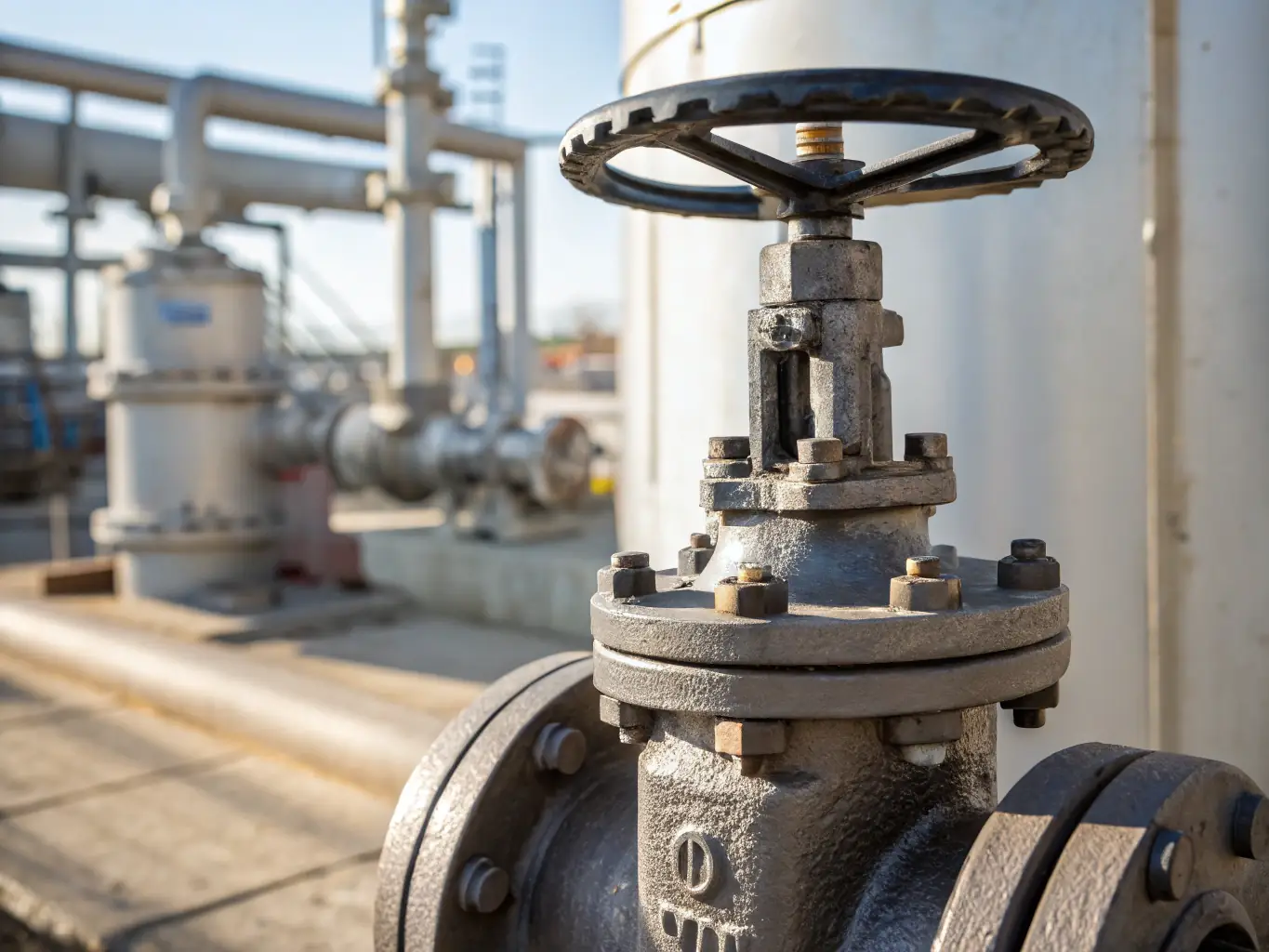
Cast Iron and Steel Fittings
Suitable for water pipelines and distribution networks
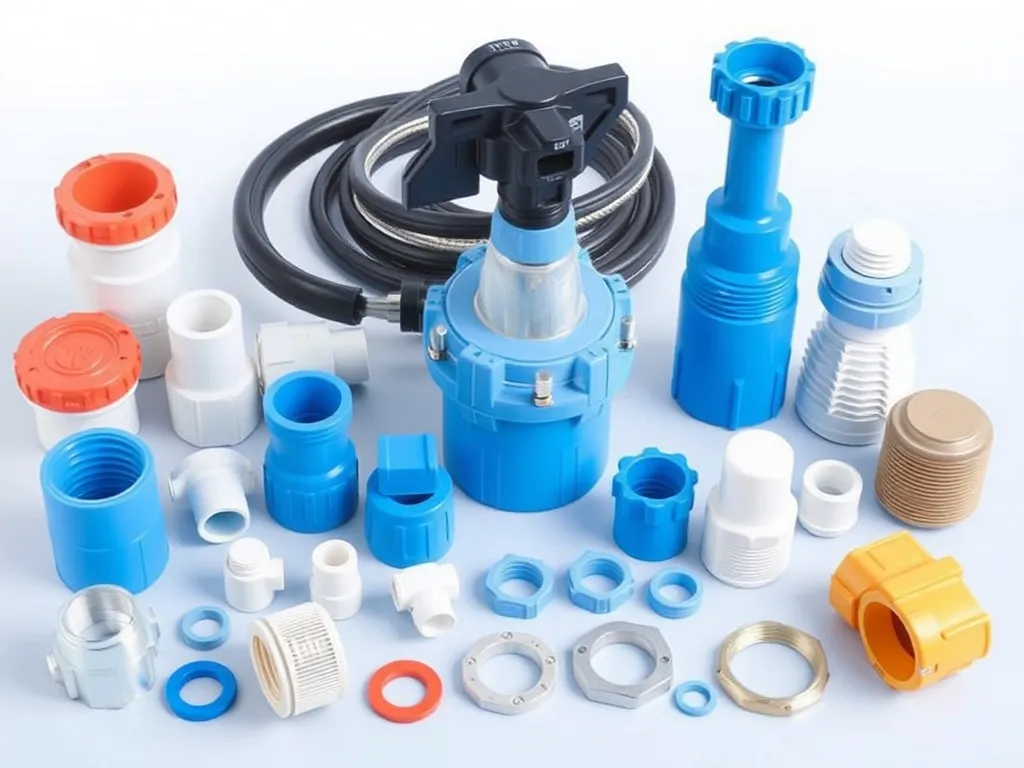
Water Connection Kits
complete kits for water service connections